Resistive Load Circuit Diagram What Is Resistive Circuit? Ex
Inductive resistive Phasor circuit resistive Power factor explained
Building Resistor Circuits Using Breadboards, Perfboards, and Terminal
Resistive load examples, properties, power consumption Understanding loads & sizing Resistive load circuit used to obtain voltage readings í µí± and í µí±
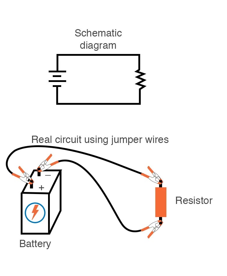
Resistor simple circuit circuits battery single end wires building parallel series components jumper current resitor alligator clip joining like method
General circuit diagram of resistive load inverter.Resistive circuits Circuit resistive protecting load seekic basic diagram3 phase resistive load calculation #1.
Phase load resistive calculationResistive loads. the circuit shown in figure 2.37 consists...get 4 (a), (b) a schematic diagram of resistive-load and complementaryResistive circuit pure waveform diagram phasor power phase current voltage resistor load ac dryer hair inductive form circuitglobe electrical loads.

Simple resistive load
Resistor circuit diagrams: understanding connections and functionsMutual inductance and basic operation Resistive inverter complementary respectively ahmedProtecting a resistive load.
Simplified circuit diagram of sampled resistive loadResistor diagrams What is a pure resistive circuit?Difference between resistive load and inductive load.
The two types of load considered. (a): resistive load. (b): resistive
3 phase resistive load calculation #2Single phase resistive load box, construction, working, applications Resistive circuits4: linear circuit with resistive load of example 2.2..
Building resistor circuits using breadboards, perfboards, and terminalResistive load circuit diagram All types of resistor symbols and diagramsResistive load simple eleccircuit.

Series resistance calculator
What is resistive circuit? example & diagramResistive examples consumption etechnog pure electrical explanation Load inductive resistive vs heater current voltage convert heat energy such same form into theySeries resistance circuit diagram resistors calculator connected showing electrical.
Resistive load approachMutual phase current inductance load resistive operation secondary voltage has basic transformers Basic source/load relationshipsResistive load circuit used to obtain voltage readings í µí± and í µí±.

Load resistive
Circuit designResistive linear circuit Loads resistive amps reactiveAssembly of the resistive load..
Load phase resistive calculationResistive purely factor explained Schematic diagram of the pure resistive load circuit.Resistive load vs inductive load.

Loads resistive consists uncharged
Single phase ac voltage controllers .
.

(a), (b) A schematic diagram of resistive-load and complementary

3 Phase Resistive Load Calculation #1 - YouTube

Difference between Resistive Load and Inductive Load - ETechnoG

Series Resistance Calculator - Inch Calculator

General circuit diagram of resistive load inverter. | Download

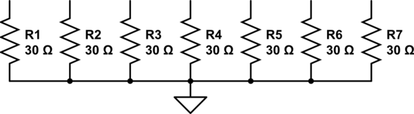
Resistive Load Circuit Diagram - Circuit Diagram